
Posts
-
Verifying Wikileaks DKIM-Signatures
Are Wikileaks emails doctored?
I’ve heard claims that emails released by Wikileaks have been doctored. I decided to try to try to test this.
Email has hidden data
From most people’s perspective Email messages have a date, to, from, subject, and body. There is potentially a lot more information that isn’t shown to users. They can also have an arbitrary number of attachments, alternative views like HTML vs plain text, an arbitrary amount of metadata, and a log of how the message got from sender to receiver. Messages often have more invisible than visible information, and some of that can be used to check the authenticity of a message. Much of the data is checked routinely in an effort to block SPAM. The default view on Wikileaks doesn’t have any of this extra data, but with a little digging I found the raw originals were available for download.
Tools for SPAM prevention can serve another purpose
Years ago I was running several mail servers as part of my day job as a sysadmin for web hosting service. It was a common occurrence for other organizations mail servers to stop accepting our outgoing mail. Mail servers do a surprising amount of work to check that everything is properly set up. Multiple Black Hole List (BHL) servers may be contacted to check of the origin of message has a good good reputation. The receiving server could try connecting back to the server of origin to see if it allows incoming connections, and if it answers with the right hello message. It could ask the sending server if it has a mailbox for the from address of the message it is in the process of trying to send. It will reverse lookup the IP address to see if the ISP knows about the domain. It will statistically analyze the message to see if it “looks legit”. It seemed like there was a new test to pass every other week. One particularly strong feature is called DomainKeys Identified Mail (DKIM) Signatures. It cryptographically signs all outgoing messages, and publishes the public key via DNS.
It’s not a perfect system
Not all servers use DKIM Signatures, but they have become very common as it’s a lot easier to get your outgoing messages accepted. There are some limitations of course. They are signed to the domain not the user. The keys tend to be smaller because they are sent via DNS, and that system switches from UDP to slower TCP with large packets. The servers could replace the key such that old email can no longer be verified. The DNS servers might not use encryption themselves. Not all headers are signed. Minor data mangling from things like converting invisible line endings from DOS to Unix can break the authentication mechanism without changing the meaning in any way.
It has a good chance of being accurate anyways
Cryptographic signatures are very difficult to spoof. I checked the signatures gmail uses, and they are of similar strength as what Bitcoin uses. Anyone who can break a key that strong could rob the world of all Bitcoins. It is more plausible that the servers signing the messages get hacked than that someone breaks the key. Their reliability is related to how well the servers with the signing keys are protected.
Checking manually
Install tools
apt-get install wget opendkim-toolsDownloading a raw email from the command line.
wget 'https://wikileaks.org/podesta-emails//get/4984'Checking the message signature.
cat 4984 | dkimverifyWith this message I get “signature ok”
Preliminary results
I only got signature validation on some of the emails I tested initially but this doesn’t necessarily invalidate them as invisible changes to make them display correctly on different machines done automatically by browsers could be enough to break the signatures. Not all messages are signed. Etc. Many of the messages that failed were stuff like advertising where nobody would have incentive to break the signatures, so I think I can safely assume my test isn’t perfect. I decided at this point to try to validate as many messages as I could so that people researching these emails have any reference point to start from. Rather than download messages from wikileaks one at a time I found someone had already done that for the Podesta emails, and uploaded zip files to Archive.org.
Emails 1-4160
Emails 4161-5360
Emails 5361-7241
Emails 7242-9077
Emails 9078-11107It only took me about 5 minutes to download all of them. Writing a script to test all of them was pretty straightforward. The program dkimverify just calls a python function to test a message. The tricky part is providing context, and making the results easy to search.
Automated testing of thousands of messages
It’s up on Github
It’s main output is a spreadsheet with test results, and some metadata from the message being tested. Results Spreadsheet 1.5 Megs
It has some significant bugs at the moment. For example Unicode isn’t properly converted, and spreadsheet programs think the Unicode bits are formulas. I also had to trap a bunch of exceptions to keep the program from crashing.
-
The long road to ubiquitous 3d cameras
It’s been almost 6 years since the first consumer 3d camera Kinect was released as an accessory for the Xbox 360. Although this was a huge leap forward, and introduced the technology to millions of people it was still a very long ways from being a must have technology. Microsoft wasn’t even friendly to developers initially. It took million view YouTube demos running on reverse engineered drivers to convince Microsoft to even release their own SDK (Software Development Kit).
Things have changed significantly with cameras released since then. Most of the bulk is gone with devices shrinking by two orders of magnitude. No more need for a power brick either. Image quality, resolution, and latency have all improved dramatically. They all have developer support too. The technology certainly doesn’t need to be perfect to gain adoption, but even with all of the improvements there are still some major hurdles. Most of the remaining ones are software.
Common features could use a common interface
Every 3d camera I know of has several common features. They produce an image where pixels are distances instead of colors. There is a factory calibration to convert depth pixels to 3d vectors, and paint them with pixels from a separate color camera. And finally they need some way to match up images taken at the same time because the color and depth images usually arrive separately. Despite all this there isn’t a common API for any of these features. There is constant innovation, so this won’t be enough for every camera but as it is software written for the original Kinect cannot be used with any newer camera without being ported to the new interface.
Beyond the hardware interface there isn’t any well defined file format to record the data. The closest to what is needed is the “bag” format that Robot Operating System (ROS) uses. It can actually store everything, but not efficiently and portably. This is pretty challenging task. Any file format needs to be able to store time synchronized images in multiple formats, and framerates at once. Since the data is commonly wanted for 3d reconstruction it should store the calibration, and any sensor data that might help align data like accelerometers, and GPS. Probably the best place to start is the Matroska media format. Raw audio is a good template for sensor data, and subtitles a good template for the NMEA GPS data.
Computer vision
This gets you to the general purpose computer vision (CV) layer which has mature open source libraries available. OpenCV has advanced features like human face detection built in, and GPU versions of many functions. It also has tools for using a calibration to turn a depth image into a point cloud (giant array of vectors). Point Cloud Library (PCL) has tools for turning point clouds into 3d surfaces.
Applications
Initially 3d cameras were being marketed for the most amazing things they could possibly do, but it turns out there are much easier killer apps to build. Simply filtering an image by distance is pretty useful. A similar tool to a green screen can be made to work with any background so long as it is further away than the subject. Face detection can be used to automatically set the cutoff range. Another simple tool is the Windows 10 “hello” feature. It can identity a user with facial recognition, and verify it isn’t just a photo by checking the shape.
The launch feature of the original kinect was skeletal tracking. The leap motion, and RealSense cameras both feature similar technology in the form of gesture recognition. This is a proprietary technology implemented in closed source software. This is how you get your Minority Report UI. Every vendor seems to have a unique API which might not be stable. For example Intel’s SDK had an emotion detection feature they licensed from a third party until Apple bought that company, and it became unavailable. I think Intel has started aggressively buying companies to prevent that from happening again, but I’m not sure that is a guarantee. There is one open source project in this space called skeltrack. The last time I checked it’s original author was too busy with his day job discovering the secrets of the universe at CERN to put much time into it.
The most obvious use for a 3d camera is 3d scanning. This could mean scanning an object, or mapping a 3d space. The algorithms usually have SLAM (Simultaneous Location And Mapping) in their name. There are fortunately a bunch of open source implementations. They are usually tricky to get working. It is possible with just cameras, but works tremendously better with motion sensors (IMU). Many vendors have some kind of solution, but it isn’t a universal feature.
Hardware availability
When I started working on the software part of this problem a year and a half ago the new intel RealSense cameras weren’t widely available yet. This made it pretty difficult to find many collaborators. The development kits haven’t been consistently available. There have also been a few computers available with built in cameras, but buying a whole computer to get a camera is a pretty expensive option. I ended up buying a computer with a camera, but it was time for an upgrade already. Fortunately the shortage is finally over as the first stand alone consumer RealSense camera started shipping today. The Razer Stargazer. The specifications of it are pretty close to being the same as the SR300 development kit. It is lighter with a detachable cable.
About a year after my first blog post on 3d cameras intel released a cross platform library for their cameras. I’m not sure how much this blog influenced them, but it does implement most of the features I described in posts last year. Their Linux support includes a kernel patch with some of my code. Their OSX support uses libuvc. Robot Operating System (ROS) has it’s own driver. Unlike my own code it has a test framework, and bugs are getting fixed rapidly. A bunch of things I was working on late last year, and early this year never got released because intel surprised me with a better implementation. Since then I’ve been focusing on the Linux kernel which has been it’s own steep learning curve.
While there are still a few rough spots with 3d cameras I think the tipping point has already been reached where the technology starts to be adopted at an exponential rate. It is also the easiest it has ever been to start developing applications.
-
RealSense 3d camera on Linux Mac OS X. infrared, calibration, point clouds
The soon to be released Intel RealSense 3d camera now has two working open source drivers. Intel’s adherence to the USB Video Class standard meant that drivers don’t need to be written from scratch, just tweaked to work with not yet standardized features to get basic functionality. The camera also has a proprietary interface with unknown capabilities that aren’t critical for it’s use as a depth capture device.
Pixel Formats
For the first two months of working with the camera I was only able to get one video format despite clearly enumerated video formats with different bits per pixel in the USB descriptors, and a list of the same 7 formats via the Linux kernel driver. I read almost all of the USB Video Class (UVC) standard, and checked the USB logs for every value of every struct as I came to them in the documentation. I was mostly looking for anything weird when setting up the infrared video stream. It seemed that infrared was just another video format. Suspecting that something was amiss with setting the format using v4l2-ctl I added code to enumerate and select a format to my depthview program. What I found was that although v4l2-ctl let me pick a pixel format by index at the kernel level the only way to pick a format was via a fourcc code that the kernel already knew about. The only way to select those other formats was to patch the kernel.
Kernel Patch
Though I’ve read through Linux Device Drivers 3rd edition, and even had some patches accepted to the kernel before they were just code cleanup. When I went to read the kernel source I was extremely lucky that the most recent patch to the uvcvideo driver was to add a video pixel format.
All it took to get 6 formats was adding them and reloading the driver of the running system. With one of the updates I made a mistake that caused a kernel segfault, but that wasn’t enough to crash the system. It’s more resilient than I thought. I haven’t sent my patch upstream yet because I was trying to figure out some details of the depth formats first. Specifically the scale of the values, and if they are linear, or exponential. Patch is available here for now.
Format Details
You may have noticed that I said 7 formats at the beginning, but in the last paragraph I said 6. The YUYV format listed first in the descriptor has an index of 2 instead of 1 so when drivers are asked for the YUYV format they return the second format instead. I haven’t tried hacking in a quirk to select index 1 to see if there really is an unselectable YUYV format. This is assumed to be a bug, but it may have been key in my first day of trying to get the camera working with Linux because it is the only format that the kernel recognized. Indexes in UVC are 1 based.
All of the fourcc codes that are officially part of the UVC standard are also the first 4 characters of the GUID in ASCII. I will refer to the formats by their 4 character ASCII names as derived from the GUID’s.
Index 2 INVZINVZ is the default format because of the indexing bug and so it’s the format described in the first 2 blog posts.
Index 3 INZI is a 24 bit format.The first 16 bits are depth data, and the last 8 are infrared.
Index 4 INVR is another 16 bit depth format.The difference from INVZ is currently unknown.
Index 5 INRI is another 24 bit 16:8 format.Presumably there are two combined formats so that either depth format can be used with infrared at the same time. The first two formats have Z, and the second two have R, this might be a pattern indicating how the four formats are grouped.
Index 6 INVI is the infrared stream by itself.

Index 7 RELI
A special infrared stream where alternating frames have the projector on, or off. Useful for distinguishing ambient lighting from projector lighting.
Second Driver
Before I patched the kernel to add pixel format support I looked for other drivers that might work without modification. I didn’t find any that worked out of the box, but I did find that libuvc was close. It has the additional advantage that it is based on libusb, and thus cross platform by default. The author Ken Tossell helped me out, but telling me what needed to be modified to add the real sense pixel formats. It turned out that wasn’t sufficient as it didn’t have support for two cameras on the same device yet. I decided to put it off until after I got calibration working, and this was fortunate because someone already had that part working. Steve McGuire contacted me on March 26 to let me know that my blog posts had been useful in getting the libuvc driver working with the real sense camera. I tested it today on Linux, and can confirm that it can produce color, infrared, and depth video. The example app regularly stopped responding so it might not be 100% ready, but it’s just a patch on an already stable driver so anything that needs to be fixed is likely to be minor. Libuvc is a cross platform driver so this probably means there is now open source driver support for MacOS, and Windows now, but I haven’t been able to test this yet.
Three Ways to Calibrate
-
The Dorabot team was the first to achieve a practical calibration on Linux. Their methodology was to write an app for the windows SDK that copied all of the mappings between color, and depth to a file, and then a library for Linux to use that lookup table. They first reported success on January 27. Their software was released on March 22.
-
I used a Robot Operating System (ROS) module to calibrate using a checkerboard pattern. My first success was March 23.
-
Steve McGuire wrote that he used a tool called vicalib
Amazon Picking Challenge
Both the Dorabot team, Steve McGuire’s team PickNik at ARPG as well as one of my crowdfunding sponsors are participants. In all cases the Intel Real Sense F200 was picked because it functions at a closer range than other depth cameras. The challenge takes place at the IEEE Robotics and Automation conference in Seattle Washington May 26-30. Maybe I’ll have a chance to go to Seattle, and meet them.
Robot Operating System (ROS)
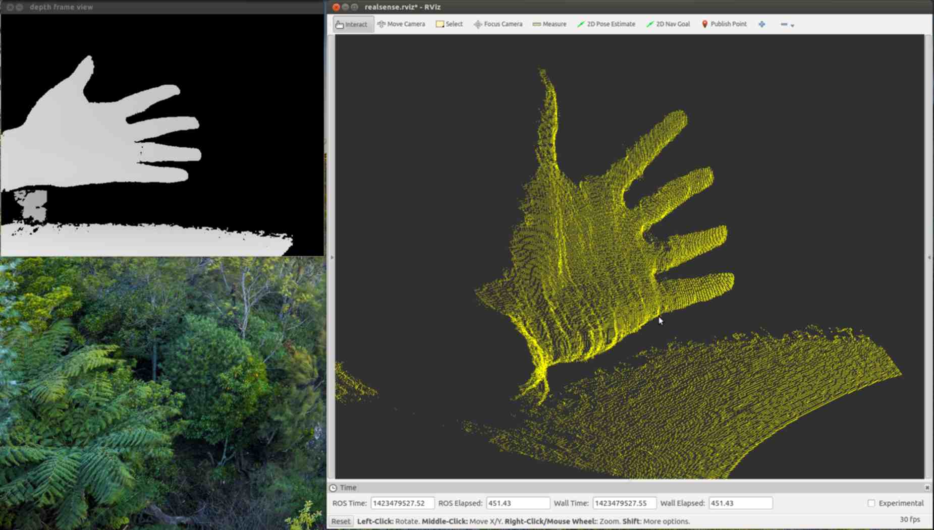
I converted my demo program depthview to be part of the ROS build system both so that I could use the ROS camera_calibration tool, and the rviz visualization tool to view generated point clouds. In the process I learned a lot about ROS, and decided it was an ideal first target platform for a Linux and MacOS SDK. The core of ROS is glue between various open source tools that are useful with robotics. Often these tools were started years ago separately, and don’t have compatible data formats. Besides providing common formats, and conversion tools it provides ways to visualize data on a running system. Parts of a running ROS system can be in the same process, separate executables, or even on different machines connected via a network. The modular approach with standard data formats is ideal for rapid prototyping. People can simultaneously work together, and autonomously without concern for breaking other peoples projects. It is also better documented than most of the individual packages that it glues together. They have their own Q and A system that acts a lot like stack overflow that has had an answer for ready for almost all of my problems. The info page for every package is a wiki so anyone can easily improve documentation. The biggest bonus is that many of the people doing research in computer vision are doing it for robotics projects using ROS.
Downside of ROS
It took me a long time to get the build system working right. There are many things to learn that have nothing to do with depth image processing. Integrating modules is easiest via networking, but that has a high serialization deserialization overhead. There are options for moving data between modules without network, or even copying overhead, but they take longer to learn. The networking has neither encryption, nor authentication support. If you are using that feature across a network you will need to do some combination of firewall, and VPN, or IPsec.
Point Clouds
Pretty much every 3d imaging device with an open source driver is supported by ROS, and that provided a lot of example code for getting a point cloud display from the Intel Real Sense 3d camera. ROS is a pubsub system. From depthview I had to publish images, and camera calibration information. Processing a depth image into a point cloud typically has two steps, getting rid of camera distortion commonly called rectifying, and projecting the points from the 2d image into 3 dimensions. Using a point cloud with rviz requires an extra step of publishing a 3d transformation between world, or map space, and the coordinate frame of the camera. There are modules for all of these things which can be started separately as separate commands in any order, or they can be started with a launch file. The first time I started up this process I skipped the rectification step to save time, and because the infrared video has no noticeable distortion even when holding a straight edge to the screen. I imagine it’s possible that the processor on the camera is rectifying the image as part of the range finding pipeline, and so that step is actually redundant. When writing my first launch file I added the rectifying step, and it started severly changing the range of many points leading to a visible cone shape from the origin to the correctly positioned points. My guess is that the image rectifying module can’t handle the raw integer depth values, and I need to convert them to calibrated floats first.
Exporting Point Clouds
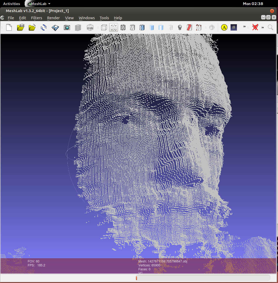
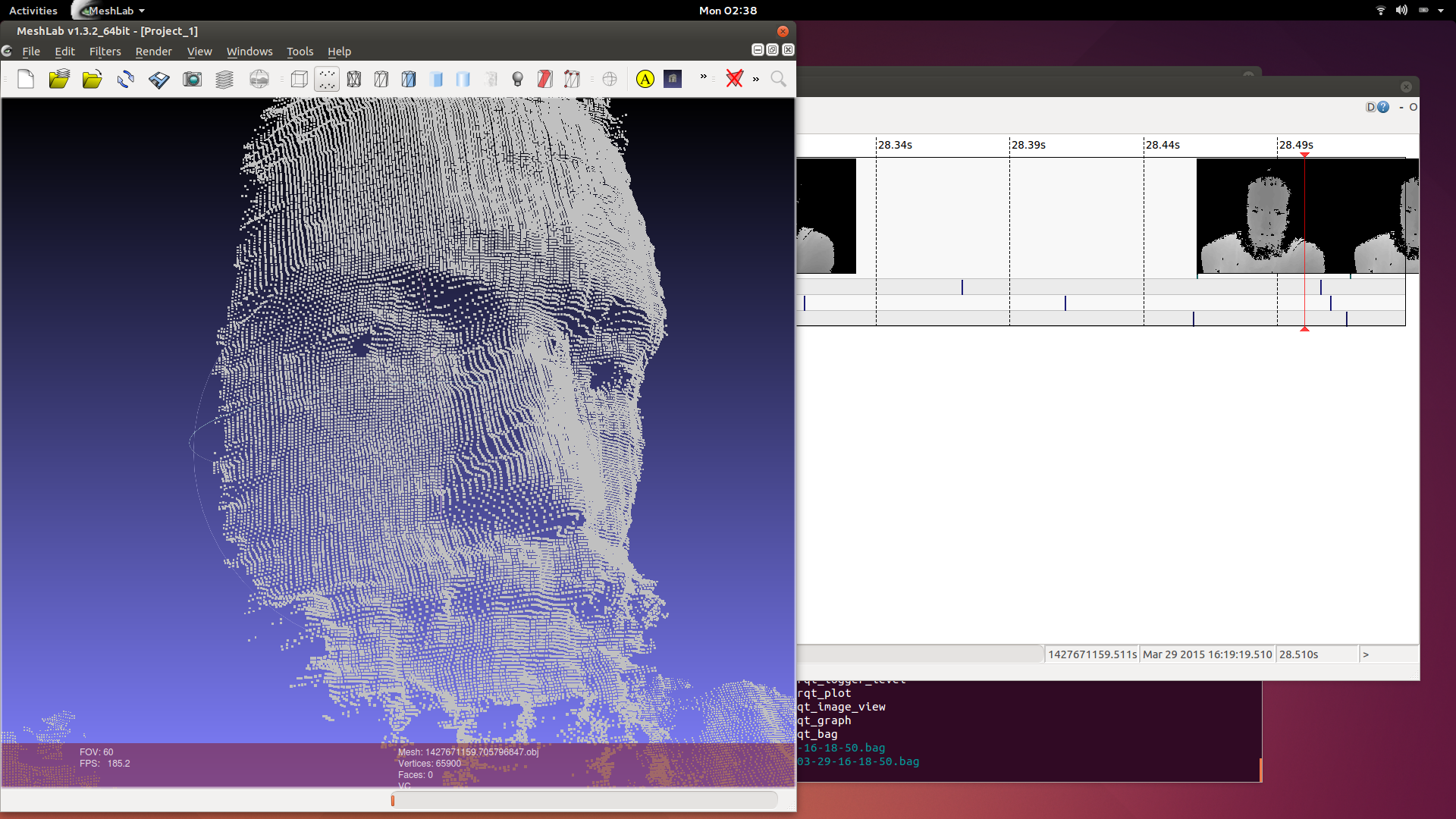
ROS has a tool for recording an arbitrary list of published data into “bag” files. To get a scan of my head I started recording, and tried to get an image of my head from every angle. Then I dumped all the point clouds with “rosrun pcl_ros bag_to_pcd”. It was surprisingly difficult to find any working tool to convert from .pcd to a 3d format that any other tool accepted. An internet search found 5 years of forum posts of frustrated people. There happened to also be an ascii version of the .pcd file format, and it looks fairly similar to the .obj file format. I converted all the files with a bash one liner.
for i in *.pcd ; do pcl_convert_pcd_ascii_binary "$i" "${i%.*}.ascii" 0; grep -v nan "${i%.*}.ascii" | sed -e '1,11d;s/^/v /' > "${i%.*}.obj" ; rm "${i%.*}.ascii" ; doneConverting Point Clouds to Meshes
This step is much harder. The only decent open source tool I’ve found is called MeshLab. It’s really designed to work with meshes more than point clouds, but there don’t seem to be any good user friendly tools for point clouds specifically. It displays, and manipulates point clouds so fast that I suspect there is no inherent reason why rviz was at max getting 15 FPS. MeshLab was getting FPS in the hundreds with the same data. I had to go through a bunch of tutorials to do anything useful, but it’s workflow is okay once you get past the learning step with one major exception. It crashes a lot. Usually 5 minutes or more into processing data with no save points. There was lots of shaking of fists in the air in frustration. Building a 3d model from point clouds requires aligning clouds from multiple depth frames precisely, and connecting the points into triangles. The solver for aligning clouds needs human help to get a rough match, and the surface finder is the part that crashes.
At the moment I don’t have a good solution, but I think ROS has the needed tools. It has multiple implementations of a tool for stitching 3d maps together called Simultaneous Location And Mapping (SLAM). It could even use an accelerometer attached to the camera to help stitch point clouds together. PCL, or point cloud library has functions to do all the needed things with point clouds it just needs a user friendly interface.
Planned Features
There are three primary features that I want to achieve with an open source depth camera sdk. The obvious 3d scanning part is started. Face tracking should be easy because OpenCV already does that. Gesture support is the hardest. There is an open source tool called Skeltrack that can find joints in human from depth images which could be used as a starting point. The founder of Skeltrack Joaquim Rocha works at CERN, and has offered to help getting it to work on the real sense camera.
Next Steps
One downside of prototyping at the same time as figuring out how something works is that it leads to technical debt at an above average pace. Since knowing how to do things right is dependent on having a working prototype refactoring is around 50% of all coding time. The primary fix that needs to be done here is setting up conditional compilation so that features with major dependencies can be disabled at compile time. This will let me merge the main branches back together. The driver interface should be split off from Qt. It should interface to both working drivers so programmers don’t have to pick which one to support. It needs to pick the right calibration file based on camera serial number as part of multiple camera support. There needs to be a calibration tool that doesn’t require ROS because ROS hasn’t been ported to Windows. The calibration tool I used was just using two features of OpenCV so that should be easy.
News updates
I’ve been posting minor updates on my crowdfunding page. If you sponsor my project for any amount of money you’ll get regular updates directly to your inbox.
Business opportunities
The companies contacting me include one of the biggest companies that exist, and one of the most valued startups ever. The interest has convinced me that I’m working on something important. Most of them want me to sign an NDA before I find out what the deal is. I can’t currently afford to pay a lawyer to tell me if it’s a good deal or not. One of the companies even wants it to be a secret that they have talked to me at all. I would rather keep a secret because I want to maintain a good relationship than because of the force of law punishing me. I don’t work well with negative reinforcement. Work I have done in the past that was under NDA has made it difficult to get work because I had nothing to show for it. This project on the other hand is very open, and it has resulted in people calling me regularly to see if I can be a part of their cool startup. That has never happened before. The one with the craziest idea for something that has never been done before will probably win. In the mean time I’ll be sleeping on my dad’s living room couch where the cost of living is low unless people crowd fund me enough money to afford first months rent.
-
-
intel Real Sense Camera on Linux part 2 3d Camera Controls
How do 3d cameras work
Speed of light
In the time it takes for one clock of 10 gigahertz ethernet light travels approximately 3 cm. A pulse of light makes a round trip so a simplistic approach will get a depth resolution of 1.5 cm. There are tricks to getting finer resolution, but most of them would lead to a device beyond the price point of what the real sense 3d camera is aiming for.
Multiple cameras
For this technique matching “features” must be detected in both images. The pixel positions of those features can be used to find the angles from each camera. The distance between cameras gives the other information needed to compute distance with the law of sines. A major advantage of this technique is that it doesn’t need to have it’s own light source, and so it works well for larger ranges such as outdoor scenes. A major drawback is that it can’t compute distances to parts of an image without distinguishing features like flat monochromatic surfaces. The real sense snapshot also known as R100 uses this technique.
Projector and camera
First lets consider the simple case of a laser range finder. All you need is a laser pointer, and a camera with fixed positions relative to each other. Scan the pixels, and find the brightest one. If the camera, and laser are lined up perfectly along a horizontal axis then the spot will only move left to right on a line. Sub pixel spot location is possible if it illuminates multiple pixels based on how brightly each is illuminated. If the center pixel of the camera is the same direction as the laser only about half of the left to right pixels can ever be illuminated as those have converging vectors, and the others have diverging vectors.
Getting a vertical line of depth is fairly easy with this technique by just adding more laser points above, and below the first one. Multiple vertical lines can be achieved by adding more points above, and below the first point. Getting a whole frame requires more tricks because it starts to get difficult to know which laser point the camera is looking at. Most laser range finders use infrared light rather than light in the visible spectrum. There are several advantages to this. Most modern lighting is designed to only emit energy in the visible spectrum for energy efficiency reasons. IR light is lower energy so it takes less power. Human eyes don’t focus IR light on the retina, and the pigments in the retina don’t readily absorb IR either so it’s much safer.
The original kinect solved this problem by having a static pseudo random “structured light” pattern of dots. The fact that the dot pattern isn’t completely regular, nor random means that the specific dot can be identified by the unique constellation it makes with nearby dots. Essentially it artificially adds features to the scene like in the multiple cameras approach. A major advantage of this approach is that the projector can be mass produced cheaply as it’s a bit like a slide projector with one slide. Disadvantages include that the dots have to be somewhat sparse so that they can be distinguished from each other. Depth cannot be reliably returned for a single dot because a constellation is required to know which dot. The grid of the point cloud isn’t regular, and that may pose problems for some algorithms.
Another structured light solution is to project multiple patterns, and determine which pixel is which based on what patterns illuminated it. The simplest of these is binary space division. Illuminate half of the projection space, and there is already enough information to narrow down which part of the projector space each camera pixel is getting. Repeat by splitting the space into 4 parts, 8, 16, etc until it is fully mapped. A frame for each situation of all pixels, and no pixels can be used to eliminate pixels that are always illuminated by direct sunlight, or never illuminated because they are made of IR absorbing material. Major advantages include a very dense point cloud of high confidence data. Major disadvantages include the need for multiple projector patterns, and camera frames per depth image, and a more complicated projector. It’s possible to use this technique with an ordinary video projector, and camera, but projectors need to be focused differently for different distances. Lasers are a big advantage because they stay in focus over large distance ranges. The intel real sense 3d camera also known as F200 is a variant of this technique.
Camera side data processing
The real sense 3d camera computes distances before sending data over USB. It’s presumed that there is custom silicon to do this, but the kinds of calculations needed are all operations that a GPU could do efficiently, and intel makes GPUs. The part might be very similar to other parts made by intel.
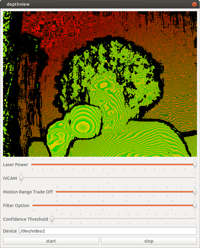
Getting the data from Linux.
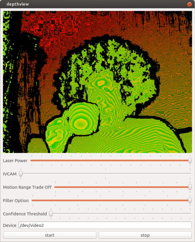
I built a reference application to demonstrate how to get depth data with a native application which I imaginatively named depthview. Depthview uses Linux syscalls to get the depth data from the Linux native drivers. The application framework is Qt. The driver interface code is currently dependent on Qt, but it should be easy to split into a separate library once more details are worked out.
The Video For Linux api version 2.0 (v4l2) has a lot of documentation, but it’s organized into chapters, and doesn’t have any examples of working programs until the appendix which isn’t how I learn programming. The reference application for v4l2 is hundreds of lines long with many functions, and that was pretty daunting at first. It was difficult for me to understand how things depended on each other when I just wanted the simplest thing possible to get video on the screen. The first key to figuring everything out is that if anything is done wrong the kernel sets an error value. Wrapping every system call in a check for errors will eliminate so much confusion.
if(-1 == ioctl(fd,/*some ioctl here*/,&data)){
    perror("/*what I was trying to do*/");
}
The second thing that really made things easier was to prototype by opening the camera on program start, and rely on process termination for cleanup.
I tried commenting out parts until I arrived at the minimum required to make it work. Most v4l2 programs I found on the internet had obvious signs of cargo culting from the appendix example program. The part that really stood out was using xioctl instead of ioctl. “xioctl” is a wrapper function used in the example program and not a part of the API at all.
The minimal version of the driver code looks something like this.
open O_NONBLOCK | O_RDWR

/* and ioctl’s in this order */

VIDIOC_S_FMT
VIDIOC_REQBUFS
VIDIOC_QUERYBUF
mmap() // function
VIDIOC_QBUF
VIDIOC_STREAMON
I think you can do it in under 50 lines of code interfacing with the driver. As soon as you want to do something more complicated like closing, and reopening the camera without closing the app the complexity increases significantly. I introduced code to keep track of state, and only do things if they were allowed in the current state. That increased the code size to around 400 lines, but eliminated the crashing. I’m sure the code size could be made smaller while still being robust.

The Qt part is basically just once a millisecond check to see if there is a video frame available. If there is then copy it into a QImage in a nested loop, and repaint. Qt has a lot of features with similar sounding names like Image, Paint, Draw, Graphics which make it easy to lose track of which does what. Naming is hard. It is only using one thread, and there is are two function calls per pixel so there is significant room for performance improvement.
Camera Controls
When I was happy enough with my application to publish it on github I started looking at what else I could figure out from the camera. The most obvious was in the USB packet log right after a long list of clearly labeled things like brightness, and contrast were a bunch of mystery settings. Around the same time engineers at Dorabot in Shenzhen had written a program for the windows SDK that listed the range, and default values of various settings. I looked at the list, and found there was a unique, and exact mapping between 5 settings, and the mystery controls.
Here is a trimmed version of the USB Log with the control name added by me in quotes.
"Laser Power"
[Interface: 0x02]
[Entity: 0x05]
[Control Selector: Unknown (0x01)]
Minimum value: 0 (0x00000000)
Maximum value: 16 (0x00000010)
Default value: 16 (0x00000010)

"IVCAM"
[Interface: 0x02]
[Entity: 0x05]
[Control Selector: Unknown (0x02)]
Minimum value: 1 (0x00000001)
Maximum value: 3 (0x00000003)
Default value: 2 (0x00000002)

"Motion Range trade off"
[Interface: 0x02]
[Entity: 0x05]
[Control Selector: Unknown (0x03)]
Minimum value: 0 (0x00000000)
Maximum value: 100 (0x00000064)
Default value: 0 (0x00000000)

"Filter Option"
[Interface: 0x02]
[Entity: 0x05]
[Control Selector: Unknown (0x05)]
Minimum value: 0 (0x00000000)
Maximum value: 7 (0x00000007)
Default value: 5 (0x00000005)

"Confidence Threshold"
[Interface: 0x02]
[Entity: 0x05]
[Control Selector: Unknown (0x06)]
Minimum value: 0 (0x00000000)
Maximum value: 15 (0x0000000f)
Default value: 6 (0x00000006)
The documentation for accessing the UVC driver directly isn’t as verbose as for v4l2. I wasn’t able to find any example code either. Fortunately the error messages are very helpful.
Here is an example of how to use one of the controls.
__u8 control = 1; // control 1 laser power
__u16 size = 0;
__u8 value = 0; /* all of the real sense extended controls are one byte,
                   checking return value for UVC_GET_LEN and allocating
                   appropriately might be better */
__u8 * data = (__u8 *)&value;
struct uvc_xu_control_query xquery;
memset(&xquery, 0, sizeof(xquery));
xquery.query = UVC_GET_LEN;
xquery.size = 2; /* size seems to always be 2 for the LEN query, but
                    doesn't seem to be documented. Use result for size
                    in all future queries of the same control number */
xquery.selector = control;
xquery.unit = 5;
xquery.data = (__u8 *)&size;

if(-1 == ioctl(fd,UVCIOC_CTRL_QUERY,&xquery)){
    perror("UVC_GET_LEN");
}
cout << "UVC_GET_LEN:" << size << endl;

xquery.query = UVC_GET_MIN;
xquery.size = size;
xquery.selector = control;
xquery.unit = 5;
xquery.data = data;
if(-1 == ioctl(fd,UVCIOC_CTRL_QUERY,&xquery)){
    perror("UVC_GET_MIN");
}
cout << "MIN:" << value << endl;

xquery.query = UVC_GET_MAX;
xquery.size = size;
xquery.selector = control;
xquery.unit = 5;
xquery.data = data;
if(-1 == ioctl(fd,UVCIOC_CTRL_QUERY,&xquery)){
    perror("UVC_GET_MAX");
}
cout << "MAX:" << value << endl;

xquery.query = UVC_GET_DEF;
xquery.size = size;
xquery.selector = control;
xquery.unit = 5;
xquery.data = data;
if(-1 == ioctl(fd,UVCIOC_CTRL_QUERY,&xquery)){
    perror("UVC_GET_DEF");
}
cout << "Default:" << value << endl;

xquery.query = UVC_GET_CUR;
xquery.size = size;
xquery.selector = control;
xquery.unit = 5;
xquery.data = data;
if(-1 == ioctl(fd,UVCIOC_CTRL_QUERY,&xquery)){
    perror("UVC_GET_CUR");
}
cout << "Current:" << value << endl;

value = 8; /* decrease laser power from 16 to 8.
              Setting stays after application quits */
xquery.query = UVC_SET_CUR;
xquery.size = size;
xquery.selector = control;
xquery.unit = 5;
xquery.data = data;
if(-1 == ioctl(fd,UVCIOC_CTRL_QUERY,&xquery)){
    perror("UVC_SET_CUR");
}
The controls are documented on intel’s website, but here is a brief overview.
Laser Power
Brightness of laser projector
IVCAM_ACCURACY
This one is really interesting in that the description on intel’s website gives some clues to how the camera works. It’s a choice between using 9, 10, or 11 structured patterns to deduce the geometry for one depth frame at 60, 55, or 50 fps. If you multiply those two numbers together you get 540, or 550 fps as the native projector and camera framerates. Consumer priced slow motion cameras are not unusual, but I’d never heard of a 550 fps projector. I did a little digging, and found that DLP projectors work by turning a pixel completely on or off, and achieving grayscale only by doing that many times per frame. I found a specification for a DLP chip of 9523 fps. The projected pattern of the real sense camera is a full on, or full off pattern so 550 fps seems feasible. I haven’t found any reference to what the camera actually uses, so this is just a guess.
If it really is able to project arbitrary IR images there is a possibility of a future SDK allowing the application of a stencil mask to the projected pattern. This would prevent it from interfering with a second real sense camera pointed at the same object. With several cameras at different angles you could capture for example a person dancing in full 3d rather than just one side of them. I’m going to imagine that those cameras are mounted to multicopters like at the CES demo.
Motion Range Trade off
At 550 fps the exposure time for each frame isn’t very long. The inverse square law dramatically affects how much light from the laser projector reaches the camera. These two facts reduce the effective range of the depth feed. This option increases the exposure time to increase the effective range. The trade off is that it lowers the depth fps, and moving objects are more likely to move faster than the series of depth frames. I don’t have a 550 fps infrared camera so I can’t tell you the exact way that it affects the pattern. This option can be anything from 0 (default) to 100.
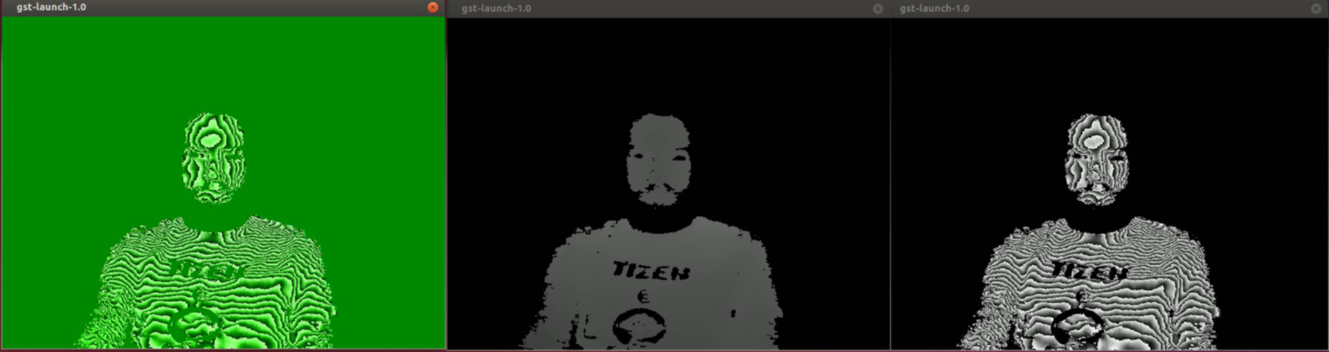
Filter
The camera has multiple filter options. There are three special filters “skeleton” which only returns points with maximum confidence, raw, and raw + gradients filter. The rest of the filters all remove some obvious artifacts in both variants of the raw data, and otherwise just differ in their range optimization.
Confidence
This setting controls what points simply get thrown away based on how the cameras internal algorithms determine a confidence value.
Calibration
A 3d camera isn’t just camera that sees depth it’s a measurement device. It’s possible to pick two points in an image, and find out the real world distance between them in cm. The camera doesn’t actually return points in XYZ though. The camera just returns a big array of distances from the camera. Pixel position can be worked out from the index into the array. Getting the XYZ value takes some more information. The two needed facts are what units are the depth values in, and how do pixel positions translate into angles. To get the color for an XYZ point in space requires more information. On many 3d cameras including the Real Sense F200 the color camera is a separate device from the depth camera. The pixel position to direction translation on the color camera is typically different than on the depth camera simply because IR has a different wavelength, and so requires a different shaped lens. The position of the color camera relative to the depth camera also needs to be known. Points are then colored by finding where pixel directions from the color camera intersect with calculated XYZ points.
There are tools to work out these numbers from images of objects with hard edges, and known measurements. One of the most common calibration targets is a checkerboard.
The Dorabot team has worked out the calibration, and sent me some screenshots of successfully generating a point cloud with colors. Unfortunately they can’t just share their calibration with everyone else who has a real sense camera because slight manufacturing variances mean every camera is unique. It is highly likely that every camera gets calibrated at the factory, and to get the calibration in Linux all that is required is to figure out how to get the information via USB.
Next Steps
The two primary things left to figure out are opening an IR stream, and getting calibration data. The IR stream must be possible because the windows API can do it. It’s possible that intel got the manufacturing perfect enough that the calibration is included in the SDK rather than on the camera so it might not exist in the USB data, but I’m certainly going to look for it. There is also some mystery as to why there are so many pixel formats for the depth stream. The guess is that there are different units of distance for pixels, such as raw vs micrometers.
Collaboration
I’ve really enjoyed communicating with other people working with the real sense camera on Linux. If you are doing the same please contact me.
References
Blog part 1
Blog part 3
Source code
How real sense camera works
Difference between R100,R200, and F200
real sense controls documentation
DorabotFunding
I’ve been working on this full time for about 47 days. I’ve raised $375, or about ⅕ of what I need to just barely pay the bills for that length of time. I’ll need to cut back to only working on this project in my spare time if I can’t raise about $1000 in the next week. If you can help out once, or on a recurring basis I can keep focusing my efforts on writing free software, and documenting this technology as clearly as I can. With your support I can hopefully have a decent set of libraries, utilities, and tutorials by they time the retail version is available and you are ready to buy.
Or
-
intel RealSense camera on Linux
Intel has started advertising for a new product that you can’t buy yet called RealSense. This is actually multiple products with a common brand name. There is the snapshot product which captures images from three lenses at once, and the other product is the 3D camera that uses structured light in the infrared spectrum similar to how the original kinect for Xbox works. I’m going to be talking about the 3D camera product as that is the one I have first hand experience with. Part of the brand is the software that goes with it on an intel based laptop, desktop, or mobile. The 3D camera does a very good job of creating a 3D point cloud but it’s not easy to transform a 3d point cloud into knowledge of what gesture someone is making with their hand. The software created by intel for their hardware is a very significant part.
Since this is a prerelease product I’m not going to take any benchmarks, as the numbers will be different by the time you can buy one. The work I have done with linux was on an Ivy Bridge CPU, and the official minimum requirements are a Haswell processor.
Comparison with original Kinect
I haven’t worked with the Xbox One version of Kinect so my comparison will only be with the original. A significant part of the design of the original Kinect was created by PrimeSense, a company now owned by Apple. They both use structured infrared light to create a depth image. They both have a color camera that is separate from the infrared camera, and this leads to imperfect matching of depth data to color.
The fundamental design difference is for range. The Kinect is designed for getting depth data for a whole room. The Real Sense 3D camera is for things less than 2 meters away. The Kinect has a motor in so that the computer can automatically adjust the tilt to get people’s whole bodies in frame. The Real Sense camera is used at a short distance so people can easily reach out to the camera, and manually adjust it. The Kinect has 4 microphones in order to beamform, and capture voice from two separate game players. The Real Sense camera only needs two to capture from one person at close range. The Kinect has a relatively grainy depth sensitivity of around a centimeter sufficient for skeleton tracking of a human. The Real Sense camera has depth precision fine enough to detect gender, emotion, and even a pulse. The Real Sense 3D camera is also much smaller comfortably resting on the top bezel of a laptop, and doesn’t require a power brick. The original Kinect is a USB 2.0 device, and that made it impossible to have the latency, or resolution of the Real Sense 3D camera.
Windows Experience
Intel treated everyone at the “Hacker Lab” very well. We were provided with a high performance laptop for the day preloaded with all the tools we needed to develop apps for the 3D camera on windows. The meals were catered, and the coffee plentiful.
The C, and C++ parts of the Beta SDK are closer to done than other parts. The binding for the javascript, and Unity libraries is clever in that is uses a daemon with a websocket to communicate. I think this means it should be possible to write a binding for any language, and work on any modern browser. I opted to use the Processing framework with java as I’ve had good luck creating 3D demos with it quickly. I was told that it’s one of the newer parts of the SDK, and not as complete. Even so I managed to get the data I needed without too much trouble. The trickiest part for me was that processing doesn’t natively support quaternions for rotation, and I managed to get the basis vectors for x, y, z, w mixed up or backwards when converting to a rotation matrix. When I got everything right I was impressed with how perfectly my rendered object matched the position, and orientation of my hand. I couldn’t notice any latency at all. I was very impressed.
Linux!
My laptop came with windows 8, and I went to a lot of trouble to setup multiboot with ubuntu, but I almost never used windows, and it was taking up half the hard drive so I nuked it a while ago. Now I want to make things with my new 3D camera that only supports Windows. Bummer. Oh wait the Kinect only lasted a week before there was open source support for it. Maybe it’s not so hard to get the Real Sense 3D camera working in the same way.
First up lets plug it in, and see what gets detected.
/:  Bus 04.Port 1: Dev 1, Class=root_hub, Driver=xhci_hcd/4p, 5000M
    |__ Port 2: Dev 16, If 0, Class=Hub, Driver=hub/2p, 5000M
        |__ Port 1: Dev 17, If 0, Class=Video, Driver=uvcvideo, 5000M
        |__ Port 1: Dev 17, If 1, Class=Video, Driver=uvcvideo, 5000M
        |__ Port 1: Dev 17, If 2, Class=Video, Driver=uvcvideo, 5000M
        |__ Port 1: Dev 17, If 3, Class=Video, Driver=uvcvideo, 5000M
        |__ Port 1: Dev 17, If 4, Class=Vendor Specific Class, Driver=, 5000M
/:  Bus 03.Port 1: Dev 1, Class=root_hub, Driver=xhci_hcd/4p, 480M
    |__ Port 2: Dev 22, If 0, Class=Hub, Driver=hub/2p, 480M
        |__ Port 2: Dev 23, If 0, Class=Audio, Driver=snd-usb-audio, 12M
        |__ Port 2: Dev 23, If 1, Class=Audio, Driver=snd-usb-audio, 12M
        |__ Port 2: Dev 23, If 2, Class=Audio, Driver=snd-usb-audio, 12M
        |__ Port 2: Dev 23, If 3, Class=Human Interface Device, Driver=usbhid, 12M
Drivers bound to it without my doing anything beyond plugging it in. The microphone array showed up in my sound control panel as a working device. I already have a built in webcam as video0. Plugging in the Real Sense camera added /dev/video1, and /dev/video2.
Video1 is just a normal 1080P color webcam, and any software that works with video was happy with it. Video2 was more difficult. It’s the source of the depth image. The problem is that the USB Video Class (UVC) doesn’t have a specification for depth as a pixel format. When applications open the camera they try to pick their favorite format, and find it doesn’t exist. Lets look at the supported formats for the Depth camera.
$ v4l2-ctl --list-formats --device=/dev/video2
ioctl: VIDIOC_ENUM_FMT

Index       : 0
Type        : Video Capture
Pixel Format: 'YUYV'
Name        : YUV 4:2:2 (YUYV)

Index       : 1
Type        : Video Capture
Pixel Format: ''
Name        : 5a564e49-2d90-4a58-920b-773f1f2

Index       : 2
Type        : Video Capture
Pixel Format: ''
Name        : 495a4e49-1a66-a242-9065-d01814a

Index       : 3
Type        : Video Capture
Pixel Format: ''
Name        : 52564e49-2d90-4a58-920b-773f1f2

Index       : 4
Type        : Video Capture
Pixel Format: ''
Name        : 49524e49-2d90-4a58-920b-773f1f2

Index       : 5
Type        : Video Capture
Pixel Format: ''
Name        : 49564e49-57db-5e49-8e3f-f479532

Index       : 6
Type        : Video Capture
Pixel Format: ''
Name        : 494c4552-1314-f943-a75a-ee6bbf0
That’s a whole lot of mystery formats. I didn’t actually notice any differences in how each format displayed. Formats can be picked by index with this command. Just replace “1” with the format you want to try.
$ v4l2-ctl --device=/dev/video2 --set-fmt-video=pixelformat=1gstreamer conveniently has a hexdump output.
$ gst-launch-0.10 v4l2src device=/dev/video2 ! fakesink num-buffers=1 dump=1Here is a snippet.
00095ef0 (0x7f00f13f9f00): 94 37 8c 37 4f 37 00 00 f7 33 c6 33 bd 33 c6 33  .7.7O7...3.3.3.3
00095f00 (0x7f00f13f9f10): cf 33 d4 33 de 33 e8 33 f2 33 13 34 17 34 0a 34  .3.3.3.3.3.4.4.4
00095f10 (0x7f00f13f9f20): f8 33 e5 33 e2 33 cd 33 c2 33 bd 33 ae 33 a5 33  .3.3.3.3.3.3.3.3
00095f20 (0x7f00f13f9f30): 91 33 73 33 5f 33 4b 33 67 33 8a 33 95 33 bd 33  .3s3_3K3g3.3.3.3
00095f30 (0x7f00f13f9f40): 07 34 2a 34 38 34 e4 33 23 33 c3 32 5e 33 8f 33  .4*484.3#3.2^3.3
00095f40 (0x7f00f13f9f50): d3 33 15 34 53 34 32 34 91 33 f0 32 97 32 60 32  .3.4S424.3.2.2`2
00095f50 (0x7f00f13f9f60): 0c 32 e2 31 e8 31 e8 31 0f 32 00 00 00 00 00 00  .2.1.1.1.2......
I guessed 16 bit little endian. You can also dump the raw binary of a frame to a file.
gst-launch-0.10 v4l2src device=/dev/video2 num-buffers=1 ! multifilesink location="frame%05d.raw"gstreamer tries to automatically determine the correct format, but in this case it needs to be told manually if you want anything other than a green topographic map appearance.
gst-launch-0.10 v4l2src device=/dev/video2 ! videoparse format=GST_VIDEO_FORMAT_GRAY16_LE width=640 height=480 ! autovideoconvert ! autovideosinkUsing the Intel SDK from Linux
The official Intel SDK is windows only, but thanks to modern virtual machines you can run windows on Linux. Since the only copy of windows I have is the system restore that came with the laptop I didn’t have anything convenient to install. I found on the Intel forums that the Real Sense SDK was reported to work with windows 10 preview.
I tried virtualbox first, and found it easy to install, but the USB passthrough supports USB 2.0, but not 3.0, and the Real Sense camera is 3.0 only because it really needs that much bandwidth.
I think Linux KVM will probably work, but it took me more than 10 minutes to figure out how to get the windows installer to run so I moved on.
VMware Player worked perfectly. It even detected the ISO as being windows 10 preview. I have found limitations in the resolution of video streams it can handle. I think this is a limitation on how fast the USB passthrough works rather than a performance issue with anything else. It is fast enough to handle the depth feed at 30 fps which is all you need to get SDK examples working. Your experience might be different with a newer computer. So far the only examples that didn’t work were because I didn’t have appropriate tools installed like the Unity development demos that require Unity. Pretty great for a prerelease product with a beta SDK on a beta OS in a virtual machine. My expectations have been exceeded.
Wireshark
It’s possible to look at the raw USB traffic with wireshark. Since the camera works fine with drivers built into Linux the primary interest would be to figure out the parts that weren’t obvious. I haven’t figured out how to get an infrared feed from Linux yet. I’m guessing that it’s activated through a vendor extension of UVC. The other mystery is if there is factory calibration data available. This produces data on the order of a gigabyte a minute so it’s a significant heap of data.
Gstreamer note
I’m using gstreamer-0.10 instead of gstreamer-1.0 because with 1.0 I have to reset the camera before each use. Physically unplugging it, and doing a USB reset both work. The software reset is much faster. See [1] for info on how to do a USB reset through software.
Conclusion
Intel’s Real Sense 3D camera is great technology. While I would love to see support in the form of an official intel SDK for Linux with all the impressive features the windows SDK has it’s not actually a requirement to use the camera included in the software development platform kit. It’s new technology so the standard doesn’t have a specification for depth formats. The standard allows for vendor extensions so intel was able to create a product that works with drivers that already exist. It’s only userspace applications that fail because they don’t know how to interpret the data they get.
Next steps
I’d like to build an app that gets the data into a point cloud, and has basic OpenGL visualization of the data as it’s recorded. I definitely want something useable with Point Cloud Library, and Meshlab. I would like to use that as the basis of a tutorial on how to use the camera to do useful things. I would also like to write a websocket app to make it easy to get the data into other applications such as a web browser.
If you like what I’m doing you could send me money so I can keep working on it full time. Crowdfund 3D
subscribe via RSS