
intel Real Sense Camera on Linux part 2 3d Camera Controls
How do 3d cameras work
Speed of light
In the time it takes for one clock of 10 gigahertz ethernet light travels approximately 3 cm. A pulse of light makes a round trip so a simplistic approach will get a depth resolution of 1.5 cm. There are tricks to getting finer resolution, but most of them would lead to a device beyond the price point of what the real sense 3d camera is aiming for.
Multiple cameras
For this technique matching “features” must be detected in both images. The pixel positions of those features can be used to find the angles from each camera. The distance between cameras gives the other information needed to compute distance with the law of sines. A major advantage of this technique is that it doesn’t need to have it’s own light source, and so it works well for larger ranges such as outdoor scenes. A major drawback is that it can’t compute distances to parts of an image without distinguishing features like flat monochromatic surfaces. The real sense snapshot also known as R100 uses this technique.
Projector and camera
First lets consider the simple case of a laser range finder. All you need is a laser pointer, and a camera with fixed positions relative to each other. Scan the pixels, and find the brightest one. If the camera, and laser are lined up perfectly along a horizontal axis then the spot will only move left to right on a line. Sub pixel spot location is possible if it illuminates multiple pixels based on how brightly each is illuminated. If the center pixel of the camera is the same direction as the laser only about half of the left to right pixels can ever be illuminated as those have converging vectors, and the others have diverging vectors.
Getting a vertical line of depth is fairly easy with this technique by just adding more laser points above, and below the first one. Multiple vertical lines can be achieved by adding more points above, and below the first point. Getting a whole frame requires more tricks because it starts to get difficult to know which laser point the camera is looking at. Most laser range finders use infrared light rather than light in the visible spectrum. There are several advantages to this. Most modern lighting is designed to only emit energy in the visible spectrum for energy efficiency reasons. IR light is lower energy so it takes less power. Human eyes don’t focus IR light on the retina, and the pigments in the retina don’t readily absorb IR either so it’s much safer.
The original kinect solved this problem by having a static pseudo random “structured light” pattern of dots. The fact that the dot pattern isn’t completely regular, nor random means that the specific dot can be identified by the unique constellation it makes with nearby dots. Essentially it artificially adds features to the scene like in the multiple cameras approach. A major advantage of this approach is that the projector can be mass produced cheaply as it’s a bit like a slide projector with one slide. Disadvantages include that the dots have to be somewhat sparse so that they can be distinguished from each other. Depth cannot be reliably returned for a single dot because a constellation is required to know which dot. The grid of the point cloud isn’t regular, and that may pose problems for some algorithms.
Another structured light solution is to project multiple patterns, and determine which pixel is which based on what patterns illuminated it. The simplest of these is binary space division. Illuminate half of the projection space, and there is already enough information to narrow down which part of the projector space each camera pixel is getting. Repeat by splitting the space into 4 parts, 8, 16, etc until it is fully mapped. A frame for each situation of all pixels, and no pixels can be used to eliminate pixels that are always illuminated by direct sunlight, or never illuminated because they are made of IR absorbing material. Major advantages include a very dense point cloud of high confidence data. Major disadvantages include the need for multiple projector patterns, and camera frames per depth image, and a more complicated projector. It’s possible to use this technique with an ordinary video projector, and camera, but projectors need to be focused differently for different distances. Lasers are a big advantage because they stay in focus over large distance ranges. The intel real sense 3d camera also known as F200 is a variant of this technique.
Camera side data processing
The real sense 3d camera computes distances before sending data over USB. It’s presumed that there is custom silicon to do this, but the kinds of calculations needed are all operations that a GPU could do efficiently, and intel makes GPUs. The part might be very similar to other parts made by intel.
Getting the data from Linux.
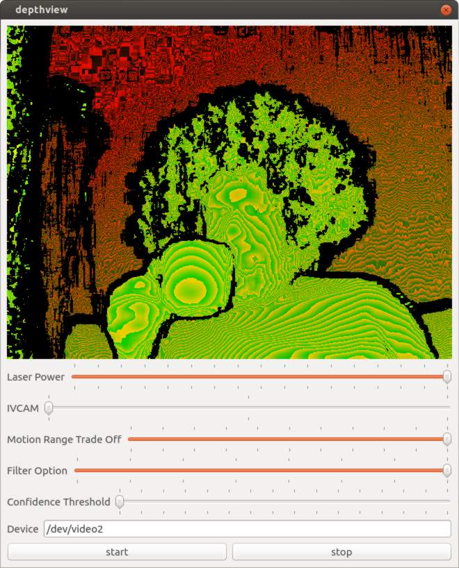
I built a reference application to demonstrate how to get depth data with a native application which I imaginatively named depthview. Depthview uses Linux syscalls to get the depth data from the Linux native drivers. The application framework is Qt. The driver interface code is currently dependent on Qt, but it should be easy to split into a separate library once more details are worked out.
The Video For Linux api version 2.0 (v4l2) has a lot of documentation, but it’s organized into chapters, and doesn’t have any examples of working programs until the appendix which isn’t how I learn programming. The reference application for v4l2 is hundreds of lines long with many functions, and that was pretty daunting at first. It was difficult for me to understand how things depended on each other when I just wanted the simplest thing possible to get video on the screen. The first key to figuring everything out is that if anything is done wrong the kernel sets an error value. Wrapping every system call in a check for errors will eliminate so much confusion.
if(-1 == ioctl(fd,/*some ioctl here*/,&data)){
    perror("/*what I was trying to do*/");
}
The second thing that really made things easier was to prototype by opening the camera on program start, and rely on process termination for cleanup.
I tried commenting out parts until I arrived at the minimum required to make it work. Most v4l2 programs I found on the internet had obvious signs of cargo culting from the appendix example program. The part that really stood out was using xioctl instead of ioctl. “xioctl” is a wrapper function used in the example program and not a part of the API at all.
The minimal version of the driver code looks something like this.
open O_NONBLOCK | O_RDWR

/* and ioctl’s in this order */

VIDIOC_S_FMT
VIDIOC_REQBUFS
VIDIOC_QUERYBUF
mmap() // function
VIDIOC_QBUF
VIDIOC_STREAMON
I think you can do it in under 50 lines of code interfacing with the driver. As soon as you want to do something more complicated like closing, and reopening the camera without closing the app the complexity increases significantly. I introduced code to keep track of state, and only do things if they were allowed in the current state. That increased the code size to around 400 lines, but eliminated the crashing. I’m sure the code size could be made smaller while still being robust.

The Qt part is basically just once a millisecond check to see if there is a video frame available. If there is then copy it into a QImage in a nested loop, and repaint. Qt has a lot of features with similar sounding names like Image, Paint, Draw, Graphics which make it easy to lose track of which does what. Naming is hard. It is only using one thread, and there is are two function calls per pixel so there is significant room for performance improvement.
Camera Controls
When I was happy enough with my application to publish it on github I started looking at what else I could figure out from the camera. The most obvious was in the USB packet log right after a long list of clearly labeled things like brightness, and contrast were a bunch of mystery settings. Around the same time engineers at Dorabot in Shenzhen had written a program for the windows SDK that listed the range, and default values of various settings. I looked at the list, and found there was a unique, and exact mapping between 5 settings, and the mystery controls.
Here is a trimmed version of the USB Log with the control name added by me in quotes.
"Laser Power"
[Interface: 0x02]
[Entity: 0x05]
[Control Selector: Unknown (0x01)]
Minimum value: 0 (0x00000000)
Maximum value: 16 (0x00000010)
Default value: 16 (0x00000010)

"IVCAM"
[Interface: 0x02]
[Entity: 0x05]
[Control Selector: Unknown (0x02)]
Minimum value: 1 (0x00000001)
Maximum value: 3 (0x00000003)
Default value: 2 (0x00000002)

"Motion Range trade off"
[Interface: 0x02]
[Entity: 0x05]
[Control Selector: Unknown (0x03)]
Minimum value: 0 (0x00000000)
Maximum value: 100 (0x00000064)
Default value: 0 (0x00000000)

"Filter Option"
[Interface: 0x02]
[Entity: 0x05]
[Control Selector: Unknown (0x05)]
Minimum value: 0 (0x00000000)
Maximum value: 7 (0x00000007)
Default value: 5 (0x00000005)

"Confidence Threshold"
[Interface: 0x02]
[Entity: 0x05]
[Control Selector: Unknown (0x06)]
Minimum value: 0 (0x00000000)
Maximum value: 15 (0x0000000f)
Default value: 6 (0x00000006)
The documentation for accessing the UVC driver directly isn’t as verbose as for v4l2. I wasn’t able to find any example code either. Fortunately the error messages are very helpful.
Here is an example of how to use one of the controls.
__u8 control = 1; // control 1 laser power
__u16 size = 0;
__u8 value = 0; /* all of the real sense extended controls are one byte,
                   checking return value for UVC_GET_LEN and allocating
                   appropriately might be better */
__u8 * data = (__u8 *)&value;
struct uvc_xu_control_query xquery;
memset(&xquery, 0, sizeof(xquery));
xquery.query = UVC_GET_LEN;
xquery.size = 2; /* size seems to always be 2 for the LEN query, but
                    doesn't seem to be documented. Use result for size
                    in all future queries of the same control number */
xquery.selector = control;
xquery.unit = 5;
xquery.data = (__u8 *)&size;

if(-1 == ioctl(fd,UVCIOC_CTRL_QUERY,&xquery)){
    perror("UVC_GET_LEN");
}
cout << "UVC_GET_LEN:" << size << endl;

xquery.query = UVC_GET_MIN;
xquery.size = size;
xquery.selector = control;
xquery.unit = 5;
xquery.data = data;
if(-1 == ioctl(fd,UVCIOC_CTRL_QUERY,&xquery)){
    perror("UVC_GET_MIN");
}
cout << "MIN:" << value << endl;

xquery.query = UVC_GET_MAX;
xquery.size = size;
xquery.selector = control;
xquery.unit = 5;
xquery.data = data;
if(-1 == ioctl(fd,UVCIOC_CTRL_QUERY,&xquery)){
    perror("UVC_GET_MAX");
}
cout << "MAX:" << value << endl;

xquery.query = UVC_GET_DEF;
xquery.size = size;
xquery.selector = control;
xquery.unit = 5;
xquery.data = data;
if(-1 == ioctl(fd,UVCIOC_CTRL_QUERY,&xquery)){
    perror("UVC_GET_DEF");
}
cout << "Default:" << value << endl;

xquery.query = UVC_GET_CUR;
xquery.size = size;
xquery.selector = control;
xquery.unit = 5;
xquery.data = data;
if(-1 == ioctl(fd,UVCIOC_CTRL_QUERY,&xquery)){
    perror("UVC_GET_CUR");
}
cout << "Current:" << value << endl;

value = 8; /* decrease laser power from 16 to 8.
              Setting stays after application quits */
xquery.query = UVC_SET_CUR;
xquery.size = size;
xquery.selector = control;
xquery.unit = 5;
xquery.data = data;
if(-1 == ioctl(fd,UVCIOC_CTRL_QUERY,&xquery)){
    perror("UVC_SET_CUR");
}
The controls are documented on intel’s website, but here is a brief overview.
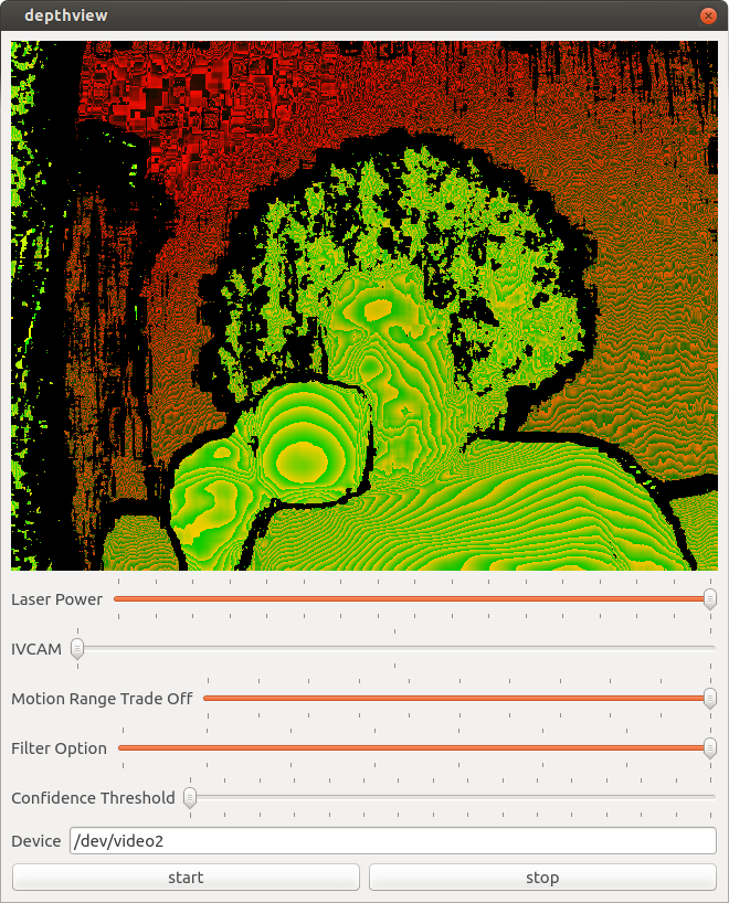
Laser Power
Brightness of laser projector
IVCAM_ACCURACY
This one is really interesting in that the description on intel’s website gives some clues to how the camera works. It’s a choice between using 9, 10, or 11 structured patterns to deduce the geometry for one depth frame at 60, 55, or 50 fps. If you multiply those two numbers together you get 540, or 550 fps as the native projector and camera framerates. Consumer priced slow motion cameras are not unusual, but I’d never heard of a 550 fps projector. I did a little digging, and found that DLP projectors work by turning a pixel completely on or off, and achieving grayscale only by doing that many times per frame. I found a specification for a DLP chip of 9523 fps. The projected pattern of the real sense camera is a full on, or full off pattern so 550 fps seems feasible. I haven’t found any reference to what the camera actually uses, so this is just a guess.
If it really is able to project arbitrary IR images there is a possibility of a future SDK allowing the application of a stencil mask to the projected pattern. This would prevent it from interfering with a second real sense camera pointed at the same object. With several cameras at different angles you could capture for example a person dancing in full 3d rather than just one side of them. I’m going to imagine that those cameras are mounted to multicopters like at the CES demo.
Motion Range Trade off
At 550 fps the exposure time for each frame isn’t very long. The inverse square law dramatically affects how much light from the laser projector reaches the camera. These two facts reduce the effective range of the depth feed. This option increases the exposure time to increase the effective range. The trade off is that it lowers the depth fps, and moving objects are more likely to move faster than the series of depth frames. I don’t have a 550 fps infrared camera so I can’t tell you the exact way that it affects the pattern. This option can be anything from 0 (default) to 100.
Filter
The camera has multiple filter options. There are three special filters “skeleton” which only returns points with maximum confidence, raw, and raw + gradients filter. The rest of the filters all remove some obvious artifacts in both variants of the raw data, and otherwise just differ in their range optimization.
Confidence
This setting controls what points simply get thrown away based on how the cameras internal algorithms determine a confidence value.
Calibration
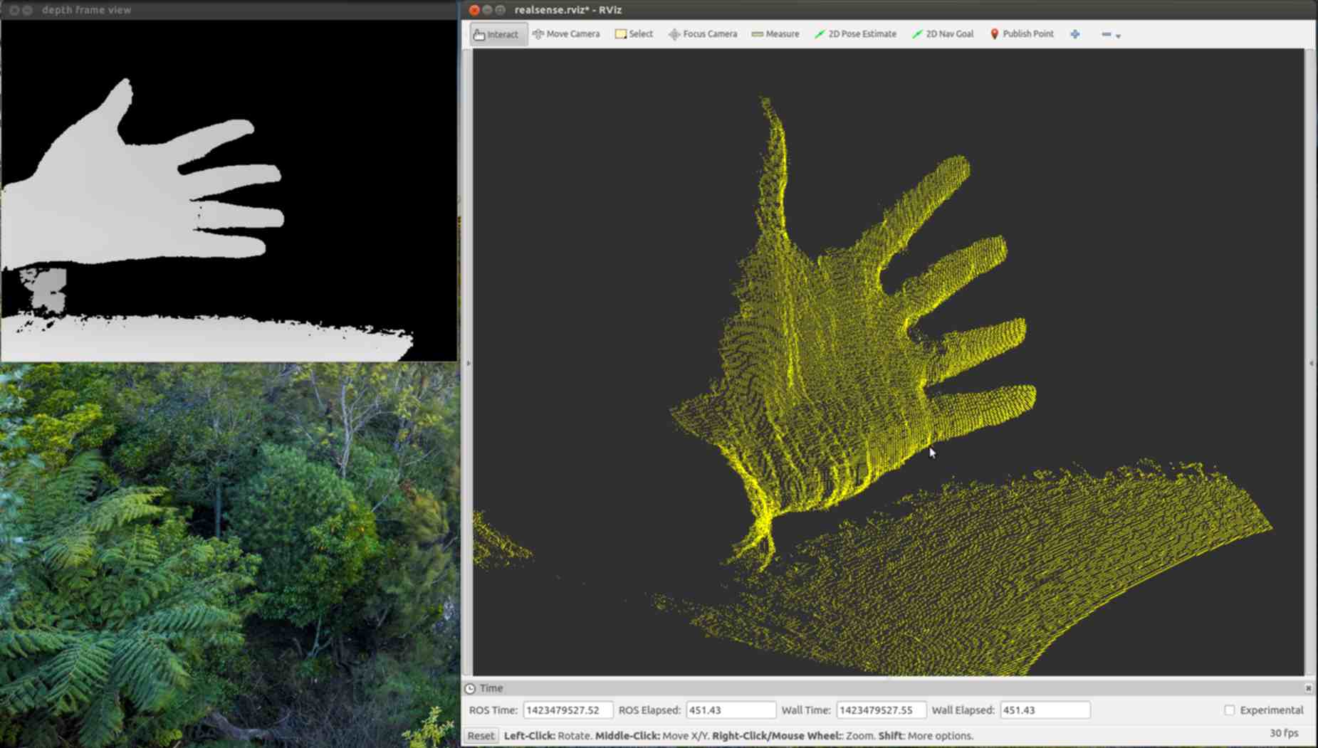
A 3d camera isn’t just camera that sees depth it’s a measurement device. It’s possible to pick two points in an image, and find out the real world distance between them in cm. The camera doesn’t actually return points in XYZ though. The camera just returns a big array of distances from the camera. Pixel position can be worked out from the index into the array. Getting the XYZ value takes some more information. The two needed facts are what units are the depth values in, and how do pixel positions translate into angles. To get the color for an XYZ point in space requires more information. On many 3d cameras including the Real Sense F200 the color camera is a separate device from the depth camera. The pixel position to direction translation on the color camera is typically different than on the depth camera simply because IR has a different wavelength, and so requires a different shaped lens. The position of the color camera relative to the depth camera also needs to be known. Points are then colored by finding where pixel directions from the color camera intersect with calculated XYZ points.
There are tools to work out these numbers from images of objects with hard edges, and known measurements. One of the most common calibration targets is a checkerboard.
The Dorabot team has worked out the calibration, and sent me some screenshots of successfully generating a point cloud with colors. Unfortunately they can’t just share their calibration with everyone else who has a real sense camera because slight manufacturing variances mean every camera is unique. It is highly likely that every camera gets calibrated at the factory, and to get the calibration in Linux all that is required is to figure out how to get the information via USB.
Next Steps
The two primary things left to figure out are opening an IR stream, and getting calibration data. The IR stream must be possible because the windows API can do it. It’s possible that intel got the manufacturing perfect enough that the calibration is included in the SDK rather than on the camera so it might not exist in the USB data, but I’m certainly going to look for it. There is also some mystery as to why there are so many pixel formats for the depth stream. The guess is that there are different units of distance for pixels, such as raw vs micrometers.
Collaboration
I’ve really enjoyed communicating with other people working with the real sense camera on Linux. If you are doing the same please contact me.
References
Blog part 1
Blog part 3
Source code
How real sense camera works
Difference between R100,R200, and F200
real sense controls documentation
Dorabot
Funding
I’ve been working on this full time for about 47 days. I’ve raised $375, or about ⅕ of what I need to just barely pay the bills for that length of time. I’ll need to cut back to only working on this project in my spare time if I can’t raise about $1000 in the next week. If you can help out once, or on a recurring basis I can keep focusing my efforts on writing free software, and documenting this technology as clearly as I can. With your support I can hopefully have a decent set of libraries, utilities, and tutorials by they time the retail version is available and you are ready to buy.
Or